| Availability: | |
|---|---|
| Quantity: | |
LD10018BUR
LITEKEY
8531200000
1.0 inch Red Alpha-numeric LED Display(LD10018BUR)
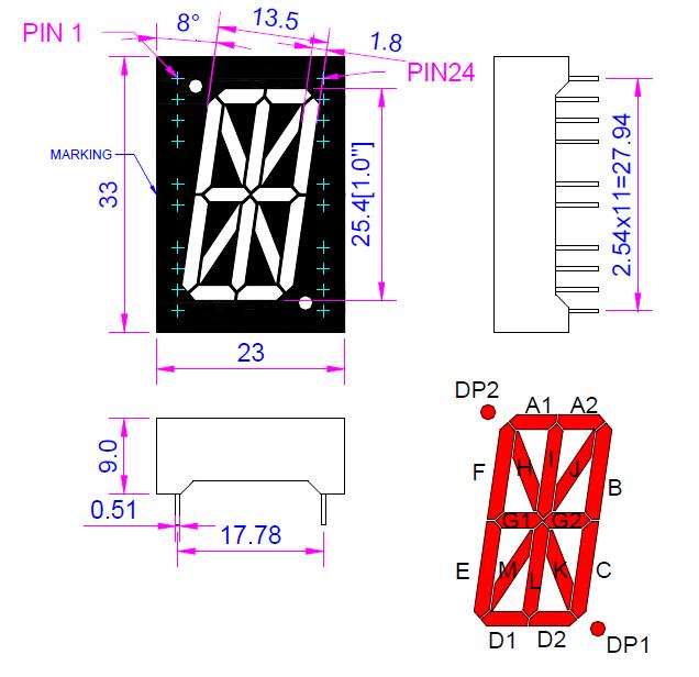
1. Outer Dumension and Internal Circuit Diagram

Notes:
All dimensions are in millimeters (inches) tolerance are 0.25mm(0.010) unless otherwise noted.
Contact us for internal circuit!
2. Characters
CHARACTERS |
| Chip Material: AlGaInP Ultra Bright Red LED Chip |
3.Absolute Maximum Ratings(Ta=25℃)
PARAMETER | SYMBOL | MAXIMUM RATING | UNIT |
Power Dissipation | PD | 78 | mW |
Peak Forward Current (1/10 Duty Cycle, 0.1 ms Pulse Width) | IPEAK | 90 | mA |
DC Forward Current | IF | 30 | mA |
Reverse Voltage | VR | 5 | V |
Electrostatic discharge | ESD | 1000 | V |
Operating Temperature Range | Topr / Tstg | -40°C to +85°C | |
Storage Temperature Range | Topr / Tstg | -40°C to +100°C | |
4. Electrical Characteristics & Absolute Maximum Ratings
PARAMETER | SYMBOL | MIN | TYP | MAX | UNIT | TEST CONDITION (Per Chip) |
Forward Voltage | VF | - | 2.0 | 2.6 | V | IF =20mA |
Luminous Intensity | IV | 30 | 45 | - | mcd | IF =20mA |
Peak Emission Wavelength | λp | - | 640 | - | nm | IF =20mA |
Dominant Emission Wavelength | λd | - | 630 | - | nm | IF =20mA |
Spectral Line Half-Width | Δλ | - | 20 | - | nm | IF =20mA |
Reverse Current | IR | - | - | 10 | uA | VR = 5V |
Contact us for more details.
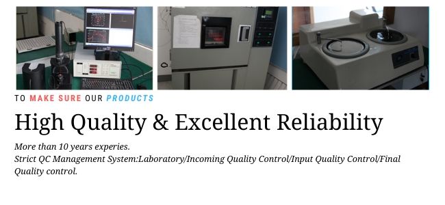
Our QC System:

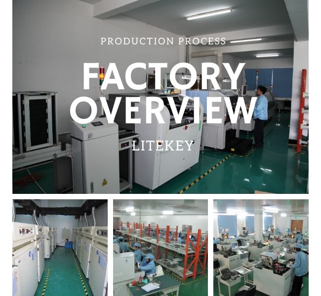
Factory Overview and production process

Our Services/Why choose LITEKEY
1. Professional service: replied within 24 hours(at workdays).
2. Various ready moldings of lamp led are available: no need to afford extra fee for moldings.
3. We also can provide customized products, design according to your demand.
4. Reliable and stable quality: 100% testing for each piece. Automatic testing and bin code selection machine.
5. Experience: produce LED components for more than 14 years.
6. Advanced Equipment: ASM automatic production machines(biggest brand in LED automatic machines)
7. Concentration: We focus on LED research and development, production and sales.
1.0 inch Red Alpha-numeric LED Display(LD10018BUR)
1. Outer Dumension and Internal Circuit Diagram

Notes:
All dimensions are in millimeters (inches) tolerance are 0.25mm(0.010) unless otherwise noted.
Contact us for internal circuit!
2. Characters
CHARACTERS |
| Chip Material: AlGaInP Ultra Bright Red LED Chip |
3.Absolute Maximum Ratings(Ta=25℃)
PARAMETER | SYMBOL | MAXIMUM RATING | UNIT |
Power Dissipation | PD | 78 | mW |
Peak Forward Current (1/10 Duty Cycle, 0.1 ms Pulse Width) | IPEAK | 90 | mA |
DC Forward Current | IF | 30 | mA |
Reverse Voltage | VR | 5 | V |
Electrostatic discharge | ESD | 1000 | V |
Operating Temperature Range | Topr / Tstg | -40°C to +85°C | |
Storage Temperature Range | Topr / Tstg | -40°C to +100°C | |
4. Electrical Characteristics & Absolute Maximum Ratings
PARAMETER | SYMBOL | MIN | TYP | MAX | UNIT | TEST CONDITION (Per Chip) |
Forward Voltage | VF | - | 2.0 | 2.6 | V | IF =20mA |
Luminous Intensity | IV | 30 | 45 | - | mcd | IF =20mA |
Peak Emission Wavelength | λp | - | 640 | - | nm | IF =20mA |
Dominant Emission Wavelength | λd | - | 630 | - | nm | IF =20mA |
Spectral Line Half-Width | Δλ | - | 20 | - | nm | IF =20mA |
Reverse Current | IR | - | - | 10 | uA | VR = 5V |
Contact us for more details.
Our QC System:

Factory Overview and production process

Our Services/Why choose LITEKEY
1. Professional service: replied within 24 hours(at workdays).
2. Various ready moldings of lamp led are available: no need to afford extra fee for moldings.
3. We also can provide customized products, design according to your demand.
4. Reliable and stable quality: 100% testing for each piece. Automatic testing and bin code selection machine.
5. Experience: produce LED components for more than 14 years.
6. Advanced Equipment: ASM automatic production machines(biggest brand in LED automatic machines)
7. Concentration: We focus on LED research and development, production and sales.
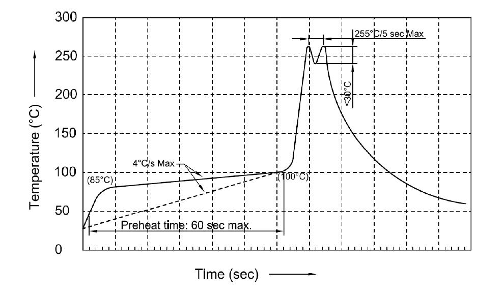
Recommended Wave Soldering Profiles

Notes:
1.Recommend pre-heat temperature of 105℃ or less (as measured with a thermocouple
attached to the LED pins) prior to immersion in the solder wave with a maximum solder bath
temperature of 260℃.
2.Peak wave soldering temperature between 245-255℃ for 3 sec (5 sec max).
3.Do not apply stress to the epoxy resin while the temperature is above 85℃.
4.Fixtures should not apply stress on the component when mounting and soldering process.
5.More than one wave soldering is not allowed.
Recommended Wave Soldering Profiles

Notes:
1.Recommend pre-heat temperature of 105℃ or less (as measured with a thermocouple
attached to the LED pins) prior to immersion in the solder wave with a maximum solder bath
temperature of 260℃.
2.Peak wave soldering temperature between 245-255℃ for 3 sec (5 sec max).
3.Do not apply stress to the epoxy resin while the temperature is above 85℃.
4.Fixtures should not apply stress on the component when mounting and soldering process.
5.More than one wave soldering is not allowed.